- 您现在的位置:买卖IC网 > Sheet目录1228 > MAX5970EVKIT+ (Maxim Integrated Products)EVAL KIT MAX5970
�� �
�
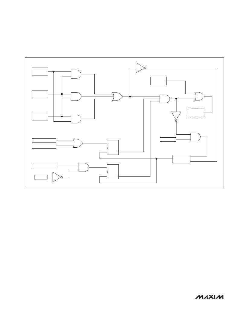
�0V� to� 16V,� Dual� Hot-Swap� Controller� with� 10-Bit�
�Current� and� Voltage� Monitor� and� 4� LED� Drivers�
�ON_�
�FORCE-ON�
�BIT�
�EN1_BIT�
�CHANNEL�
�EN2_BIT�
�ENABLED�
�ANALOG� SLOW_TRIP�
�S�
�Q�
�RETRY� PIN�
�ANALOG� FAST_TRIP�
�R�
�Q�
�200ms� DELAY,�
�THEN� PULSE�
�UV/OV� CRITICAL�
�PROT�
�S�
�R�
�Q�
�Q�
�Figure� 1.� Channel� On-Off� Control� Logic� Functional� Schematic�
�To� determine� the� output� dV/dt� during� startup,� divide�
�the� GATE_� pullup� current� I� G(UP)� by� the� gate-to-ground�
�capacitance.� The� voltage� at� the� source� of� the� external�
�MOSFET� follows� the� gate� voltage,� so� the� load� dV/dt� is�
�the� same� as� the� gate� dV/dt.� Inrush� current� is� the� product�
�of� the� dV/dt� and� the� load� capacitance.� The� time� to� start�
�up� t� SU� is� the� hot-swap� voltage� VS_� divided� by� the� output�
�dV/dt.�
�Be� sure� to� choose� an� external� MOSFET� that� can� handle�
�the� power� dissipated� during� startup.� The� inrush� cur-�
�rent� is� roughly� constant� during� startup,� and� the� voltage�
�drop� across� the� MOSFET� (drain� to� source)� decreases�
�linearly� as� the� load� capacitance� charges.� The� resulting�
�power� dissipation� is� therefore� roughly� equivalent� to� a�
�single� pulse� of� magnitude� (VS_� x� Inrush� current)/2� and�
�duration� t� SU� .� Refer� to� the� thermal� resistance� charts� in�
�the� MOSFET� data� sheet� to� determine� the� junction� tem-�
�perature� rise� during� startup,� and� ensure� that� this� does�
�not� exceed� the� maximum� junction� temperature� for� worst-�
�case� ambient� conditions.�
�Circuit-Breaker� Protection�
�As� the� channel� is� turned� on� and� during� normal� opera-�
�tion,� two� analog� comparators� are� used� to� detect� an�
�overcurrent� condition� by� sensing� the� voltage� across�
�an� external� resistor� connected� between� SENSE_� and�
�MON_.� If� the� voltage� across� the� sense� resistor� is� less�
�than� the� slow-trip� and� fast-trip� circuit-breaker� thresholds,�
�the� GATE_� output� remains� high.� If� either� of� the� thresholds�
�is� exceeded� due� to� an� overcurrent� condition,� the� gate�
�of� the� MOSFET� is� pulled� down� to� MON_� by� an� internal�
�500mA� current� source.�
�The� higher� of� the� two� comparator� thresholds,� the� fast-�
�trip,� is� set� by� an� internal� 8-bit� DAC� (see� Table� 8),�
�within� one� of� three� configurable� full-scale� current-sense�
�ranges:� 25mV,� 50mV,� or� 100mV� (see� Tables� 7a� and� 7b).�
�The� 8-bit� fast-trip� threshold� DAC� can� be� programmed�
�16�
�_____________________________________________________________________________________�
�发布紧急采购,3分钟左右您将得到回复。
相关PDF资料
MAX5976BEVKIT+
EVAL KIT MAX5976B
MAX5977AEVKIT#
EVAL KIT MAX5977A
MAX5980EVKIT#
EVAL KIT MAX5980
MAX5982CEVKIT#
EVAL KIT MAX5982C
MAX6397SATA+T
IC SW OVERVOLT PROT 8-TDFN
MAX6496EVKIT+
KIT EVAL FOR MAX6496
MAX6651EVKIT
EVAL KIT FOR MAX6651
MAX7325EVKIT+
KIT EVAL FOR MAX7325
相关代理商/技术参数
MAX5971AETI+
功能描述:热插拔功率分布 IEEE 802.3af/at PSE Controller RoHS:否 制造商:Texas Instruments 产品:Controllers & Switches 电流限制: 电源电压-最大:7 V 电源电压-最小:- 0.3 V 工作温度范围: 功率耗散: 安装风格:SMD/SMT 封装 / 箱体:MSOP-8 封装:Tube
MAX5971AETI+T
功能描述:热插拔功率分布 IEEE 802.3af/at PSE Controller RoHS:否 制造商:Texas Instruments 产品:Controllers & Switches 电流限制: 电源电压-最大:7 V 电源电压-最小:- 0.3 V 工作温度范围: 功率耗散: 安装风格:SMD/SMT 封装 / 箱体:MSOP-8 封装:Tube
MAX5971AETI+W
制造商:Maxim Integrated Products 功能描述:IEEE802.3 AT PSE SWITCH - Rail/Tube
MAX5971AEVKIT
功能描述:电源管理IC开发工具 RoHS:否 制造商:Maxim Integrated 产品:Evaluation Kits 类型:Battery Management 工具用于评估:MAX17710GB 输入电压: 输出电压:1.8 V
MAX5971AEVKIT+
制造商:Maxim Integrated Products 功能描述:PD INTERFACE CONTROLLER - Boxed Product (Development Kits)
MAX5971BETI
制造商:Maxim Integrated Products 功能描述:
MAX5971BETI+
功能描述:热插拔功率分布 IEEE 802.3af/at PSE Controller RoHS:否 制造商:Texas Instruments 产品:Controllers & Switches 电流限制: 电源电压-最大:7 V 电源电压-最小:- 0.3 V 工作温度范围: 功率耗散: 安装风格:SMD/SMT 封装 / 箱体:MSOP-8 封装:Tube
MAX5971BETI+T
功能描述:热插拔功率分布 IEEE 802.3af/at PSE Controller RoHS:否 制造商:Texas Instruments 产品:Controllers & Switches 电流限制: 电源电压-最大:7 V 电源电压-最小:- 0.3 V 工作温度范围: 功率耗散: 安装风格:SMD/SMT 封装 / 箱体:MSOP-8 封装:Tube